
What Is a Pneumatic System? Components, Working Principle & Diagram Explained
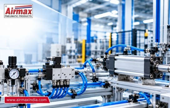
Walk through almost any factory and you will hear it before you see it: a short hiss, a thud, a hiss again. That is compressed air at work, pushing a clamp shut, lifting a part or sliding a product onto a conveyor. The thing behind that sound is a pneumatic system.
If you are new to the subject, or you maintain a machine and never learned how the air side of it fits together, this guide walks through the whole path from the air intake to the moving rod. It covers what each component does, how the system works step by step, and what tends to go wrong.
What is a pneumatic system?
Pneumatics means using pressurized air or gas to produce mechanical motion. In industry, that usually means compressed air, supplied by a central electric compressor, driving cylinders, air motors and other actuators [1]. Put more simply, a pneumatic system is a way to move energy around a plant using air in pipes instead of wires or oil.
The idea is old. Ctesibius of Alexandria, who worked in the early 3rd century BCE, is often called the “father of pneumatics” [1]. What has changed is the scale. Today the same principle is used in factory automation, medical and dental equipment, and the air brakes on buses, trucks and trains [1][2].
How a pneumatic system works, step by step
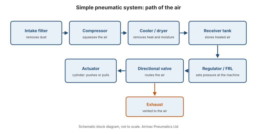
Different sources break the process into slightly different numbers of steps, but the order is the same [2][4]:
- Air comes in through a filter. The filter removes dust and other contaminants before the air reaches the compressor.
- The compressor squeezes it. The compressor draws air into a chamber and compresses it into a smaller volume [4]. Doing this makes the air very hot [2].
- The air is cooled and dried. A cooler brings the temperature down, and a dryer or water separator removes moisture [2][4].
- It waits in a receiver tank. The tank stores treated air so there is a steady supply when the machine asks for it [4].
- Pressure is set. Regulators hold pressure at the level the equipment needs [2].
- Air travels through tubing to a valve. A directional control valve decides where the air goes [2][4].
- The actuator moves. A cylinder or rotary actuator turns air pressure into linear or rotary motion [3].
- Exhaust leaves. Used air goes back through the valve and is vented to the atmosphere [2].
A simple flow diagram
The main components and what each one does
Compressor
The compressor is the power source. It is usually driven by an electric motor, and some are driven by diesel engines [2]. Its rating is given in flow and pressure [5]. If it is too small, you get low pressure or weak airflow. If it is too large, you waste energy [4].
Cooler, dryer and water separator
Compression heats the air and leaves moisture behind. A cooler and dryer remove both, because water can damage or clog downstream parts [2]. Moisture left in the air can also corrode valve bodies and cylinder bores [5].
Receiver tank
The tank stores compressed air and smooths out pressure swings [5]. One source gives an allowable swing of about ±0.5 bar in a typical setup [5]. Think of it as a buffer between the compressor and the machine.
FRL unit (filter, regulator, lubricator)
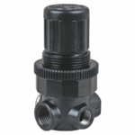
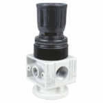
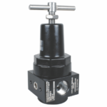
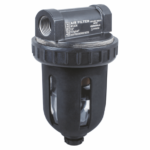
This unit sits close to the point of use and does three jobs. The filter takes out leftover moisture and dirt, the regulator keeps pressure within limits, and the lubricator adds a light film of oil where it is needed [4].
Two cautions apply here. A regulator controls pressure but not flow, so it is often paired with a flow control valve [3]. And a filter-regulator on its own does not remove oil vapor or chemical contaminants, so extra filtration may be needed [3]. On lubrication, sources do not all say the same thing. One says lubricators are often unnecessary because modern cylinders are typically lubricated for life [2], and another warns that lube-free components should not receive oil from a lubricator [5]. Check the manual for your cylinders and valves before adding oil.
Directional control valves
These valves send air to the right port at the right time. They are named by their ports and positions [4]:
- 2-way: one inlet and one outlet, so it either allows or stops flow.
- 3-way: adds an exhaust port that vents the outlet when the inlet is blocked.
- 4-way: one inlet, one exhaust and two outlets, commonly used with double-acting cylinders.
- 5/2: five ports and two positions, such as extend and retract.
- 5/3: five ports and three positions. The center position blocks all ports, which lets an actuator stop partway through its stroke.
Flow control valves
These set how fast the actuator moves. On a cylinder, flow controls are often fitted to the ports so they meter the exhaust air and set the speed [5].
Actuators
This is where the work happens. A linear actuator (a cylinder) moves in a straight line, and a rotary actuator moves in a circle [4]. Output force depends on bore size, and a larger bore gives more force [3]. The basic relationship is force equals pressure times piston area [5].
Cylinders come in two main kinds. A single-acting cylinder has one air port and a spring return, with a limited stroke and lower air use. A double-acting cylinder has two ports and uses air for both strokes [3]. For a closer look at the double-acting design, see our post on how a double acting pneumatic cylinder works.
Tubing, fittings and silencers
Tubing and fittings carry the air and connect the parts. Mufflers and silencers vent the exhaust and cut down noise [3]. Exhaust noise is one of the known drawbacks of pneumatics, and silencers are the usual fix [5].
What pressure do pneumatic systems run at?
You will see different numbers depending on the source, because they describe different points in the system. One source says most industrial pneumatic applications use 80 to 100 psi (550 to 690 kPa) [1]. Another gives stored receiver pressure of 5 to 10 bar (72 to 145 psi) and regulated working pressure of typically 4 to 6 bar for general cylinders [5]. A third advises designing the system around the lowest-rated component, which in its example is in the 60 to 80 psi range [2].
The practical lesson is to check the rating on your own cylinders and valves, then set the regulator to suit. Too little pressure gives poor performance, and too much can cause a failure [2].
Where pneumatic systems are used
Examples from the sources include packaging machines, vacuum grippers and pick-and-place work, automotive assembly, dental drills, jackhammers, nail guns and HVAC controls [1][2]. For more industry examples, see our post on pneumatics in automotive and food and beverage industries.
Strengths and limits
What pneumatics does well
- Air is cheap and easy to get, and the parts are simple [2][4].
- Cycles are fast, with strokes done in milliseconds [2][5].
- There is no oil leak to clean up and no fire hazard from hydraulic oil [1][4].
- It can be used in explosive environments, because no electrical energy is needed at the actuator [4][5].
- Gas absorbs shock, which reduces damage to equipment [1].
Where it falls short
- Air compresses, so precise positioning is harder [5]. Electric actuators offer better precision and repeatability [2].
- Force density is lower than hydraulics, so very high forces may need hydraulic or electric actuators [3][5].
- Making compressed air takes energy, and leaks waste it [2][5].
- Moisture and noise both need managing [5].
For a direct comparison, one source lists typical hydraulic pressures at 1,000 to 5,000 psi (6.9 to 34.5 MPa), against 80 to 100 psi for most industrial pneumatics [1]. That gap is why hydraulics handles heavy loads better. Our pneumatic vs hydraulic comparison covers when to pick which.
What usually goes wrong
According to one source, pressure drop is the most common failure, and the usual causes are clogged filters, undersized or badly routed piping, and leaks at couplings, hoses, fittings and joints [4]. Another says routine maintenance, including filter changes, hose checks and silencer servicing, is needed to prevent breakdowns [2].
If your machine feels weak or slow, work through the air path in order: compressor output, filter condition, regulator setting, leaks, then valve and cylinder. Two of our posts help here: a pneumatic system preventive maintenance checklist and a guide to finding and fixing compressed air leaks.
Where Airmax products fit
Airmax Pneumatics Ltd has made pneumatic products in Ahmedabad since 1992, and lists ISO and CE certifications for its valve and cylinder products (see our certificates page). Several of the parts in the diagram above are things we make:
- Pneumatic cylinders, in single-acting and double-acting types. The range as a whole is listed with bores from 12 mm to 500 mm and strokes from 10 mm to 2000 mm [6]. Check the datasheet for any single model.
- Directional control valves, including the poppet solenoid valve.
- FRL units, in several series.
- Moisture separators, which are listed alongside drain valves and a microfine filter.
- Pneumatic accessories for connecting it all.
Need help specifying a system?
Tell us about your machine: the load, the stroke, the air pressure you have, and where it will run. We can help you match cylinders, valves and air preparation. You can contact our team or download the product catalogue.
References
- Wikipedia. “Pneumatics.” https://en.wikipedia.org/wiki/Pneumatics
- Airline Hydraulics. “What is a Pneumatic System? Guide to Components and Applications.” https://blog.airlinehyd.com/pneumatic-system-explainer
- Pneumatic Tips (Norgren). “An Introduction to Pneumatic Systems & Actuators.” https://www.pneumatictips.com/pneumatic-systems-an-introductory-primer-and-actuator-selection-guide/
- Tavoron (formerly JH Foster). “Understanding Your Pneumatic System Components.” https://tavoron.com/resources/blog/understanding-your-pneumatic-system-components/
- PLCprogramming.io. “Pneumatics Basics 2026.” https://plcprogramming.io/blog/pneumatics-basics
- Airmax Pneumatics Ltd. “Pneumatic Cylinder.” https://www.airmaxindia.com/products/pneumatic-cylinder/