
ISO 5599 Pneumatic Valve Standards & Symbols Explained (Beginner’s Guide)
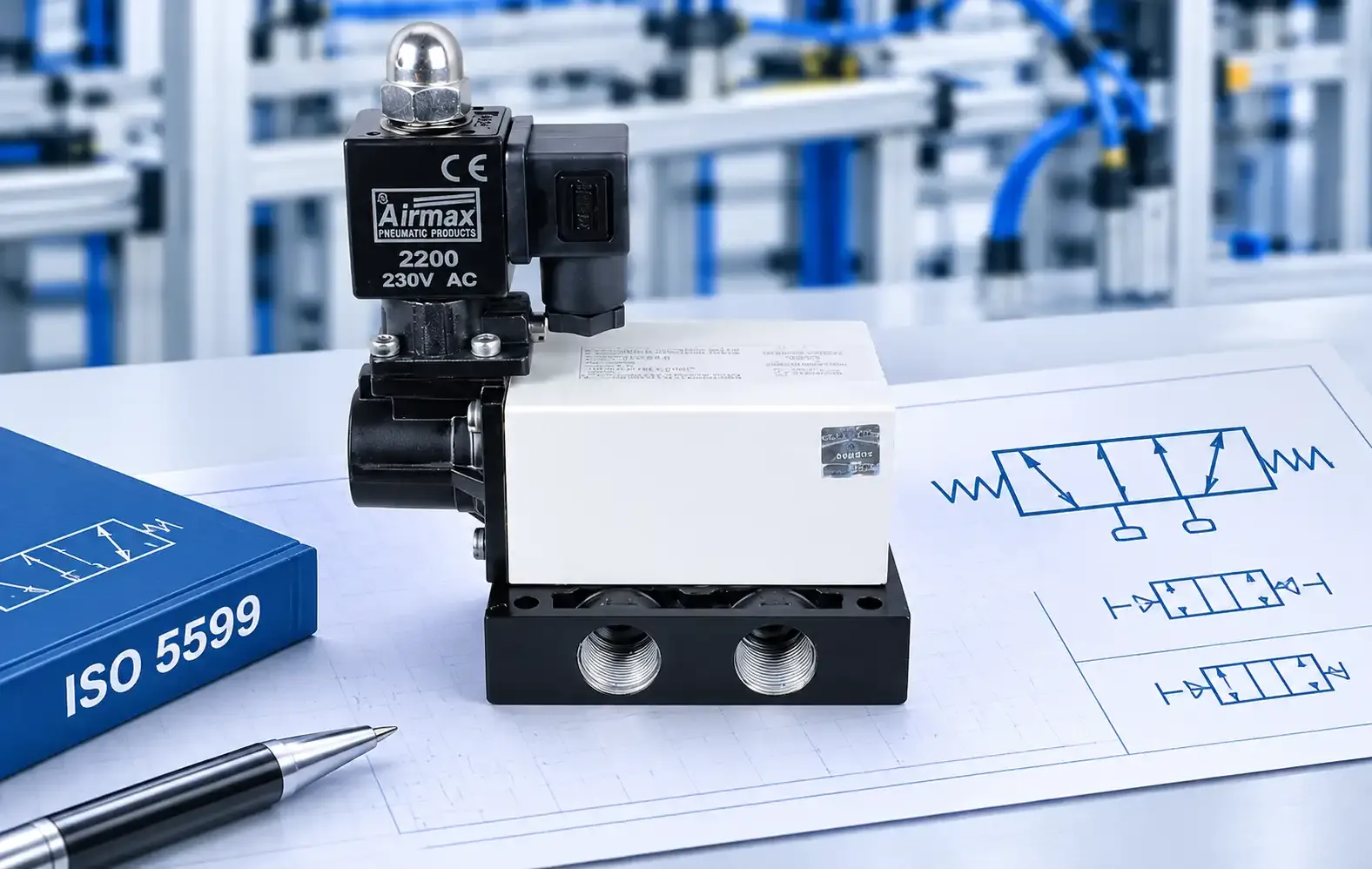
Open a pneumatic valve datasheet for the first time and you are met with a pile of codes. “5/2”. “ISO 5599-1”. Port numbers like 1, 2, 4 and 12. A small drawing of two squares with arrows inside. Nobody explains that these come from different standards, and each one answers a different question.
This guide sorts that out. You will learn what ISO 5599 covers (and what it leaves out), what the port numbers mean, and how to read a valve symbol. It is written for people who work with pneumatic machines but never had a reason to read a standard.
A quick note on sources: I have used the published standards pages and previews, plus two manufacturer and distributor guides for the beginner explanations. Where I am giving my own reading of something, the text says so.
Short answer: one standard does not do everything
People often say “ISO 5599” when they mean the whole bundle of valve rules. In practice, four different standards are involved:
| The question you are asking | Where the answer comes from |
| Will this valve fit that base or manifold? | ISO 5599-1 and ISO 5599-2 (mounting interfaces) [1][2][3] |
| What do port numbers like 1, 2, 4, 12 and 14 mean? | ISO 11727, which follows the numbering used in ISO 5599 [5] |
| How is the valve drawn on a circuit diagram? | ISO 1219-1 [6][9] |
| Are there smaller valve sizes with their own interface? | ISO 15407 [7] |
ISO 5599 is not a symbol standard. That is the most common mix-up, so it is worth keeping in mind as you read on.
What ISO 5599 actually covers
The full title of the series is “Pneumatic fluid power: Five-port directional control valves”. It has three parts:
A “mounting interface surface” is the flat face where a valve sits on a sub-base or manifold. According to the preview of Part 1, the standard specifies the dimensions and tolerances of the interface features, the port identification, and how the result of operating a control mechanism is identified. It also says that it does not apply to the functional characteristics of interfaces [2]. Sizes 1, 2 and 3 appear in the first table of dimensions, and sizes 4, 5 and 6 in the second [2].
Part 2 adds the dimensions and specifications for an electrical connector, and states a maximum rated pressure of 1.6 MPa (16 bar) [3].
What that means in plain terms
My reading is this: ISO 5599 fixes the footprint. It tells valve makers where the holes and ports sit on the mounting face, so a valve made to the standard can sit on a matching base. It does not decide how much air the valve flows, what voltage the coil takes, or how long it lasts. The standard itself says it leaves out functional characteristics [2], and the code system in Part 3 is described as unsuitable for direct application to products because it does not describe attributes that affect performance interchangeability [4].
So two valves that fit the same base can still differ. Always read the datasheet for flow, pressure rating and electrical details.
Which parts are still current?
That last point matters if you see a “valve function code” quoted in an older catalog. The code system was meant for communication between people, and it covered valve operator functions for mounting surfaces that follow ISO 5599-1 [4]. Since it has been withdrawn, treat any such code as a manufacturer’s shorthand and confirm what it means.
The smaller sizes: ISO 15407
If you work with compact valves, you may also meet ISO 15407. Part 2 of that series covers five-port valves in sizes 18 mm and 26 mm, with mounting interface surfaces and an optional electrical connector, at a maximum rated pressure of 1.6 MPa (16 bar) [7]. Like ISO 5599, it says it does not apply to the functional characteristics of interfaces [7].
What the port numbers mean
Port numbers are covered by ISO 11727, which sets rules for identifying and marking ports on pneumatic directional control valves. It says numerals are the main method, not letters, and that the numbering follows ISO 5599-1, -2 and -3 [5].
For the main ports, the pattern is simple [5]:
For control mechanisms such as a solenoid or a pilot signal, ISO 11727 uses two-digit numbers. The first digit is always 1, and the second digit is the main port that gets connected to port 1 when that control is actuated. A second digit of 0 means actuating the control blocks port 1 [5].
That is why you see these two numbers so often:
Once you know the rule, “12” and “14” stop looking random. They simply tell you which outlet gets the supply air.
Some catalogs use letters instead. One distributor guide says manufacturers use different letters but lists these as fairly standard: P for the pressure inlet, A and B for the outlets (usually going to the extend and retract ports of a cylinder), and R and S for the exhausts [9]. If you are comparing two datasheets, check whether one uses numbers and the other letters.
How to read a valve symbol
The symbols themselves come from a different standard. ISO 1219-1:2012 covers graphical symbols for fluid power components, and sets out the basic elements and the rules for building symbols [6]. ISO lists it as published and reviewed in 2017, with an amendment added in 2016 [6]. Another guide notes that pneumatic symbols follow ISO 1219 and ISO 14617 [9].
Here is the key idea: a symbol shows what a valve does, not what it looks like. Most valve symbols have three parts: actuators, position boxes and ports [9].
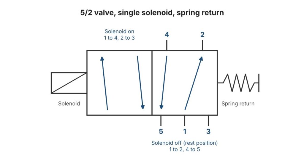
A 5/2 single solenoid, spring return valve symbol
Worked example: a 5/2 solenoid and spring valve
Take a 5/2 valve with a solenoid on one side and a spring on the other. To keep the example simple, assume the solenoid is the control that gives the “14” result described above.
If port 2 feeds one end of a double acting cylinder and port 4 feeds the other, energizing the solenoid moves the cylinder one way, and switching it off lets the spring move it back. The port results above come from ISO 5599-1, and which end of the cylinder each port feeds depends on how you pipe it.
What 3/2, 5/2 and 5/3 mean
Valve names follow a “ports/positions” pattern. A 3/2 valve has three ports and two positions, and a 5/3 valve has five ports and three positions [8]. Festo’s guide lists 3/2, 5/2 and 5/3 as the most commonly used [8]:
If you are still deciding between cylinder types, our post on how a double acting pneumatic cylinder works explains why a double acting cylinder pairs with a 5/2 valve.
Two small traps to know about:
It also helps to know the difference between monostable and bistable valves. A monostable valve returns to its rest position when the signal is removed. A bistable valve stays where it was switched until a second signal returns it [8]. Having two coils does not make a valve bistable. A 5/3 valve with two coils and two return springs is still monostable [8].
A simple checklist for choosing a valve
Airmax directional control valves
Airmax Pneumatics Ltd has made pneumatic products in Ahmedabad since 1992. Our directional control valve range lists five series: the AD-20 series, the RM series, the poppet solenoid valve, the Siko series and the AMV series [10]. The Siko page, for example, lists 3/2, 5/2 and 5/3 valves with roller lever, push-pull and hand lever operation.
If you need a valve for a specific mounting interface, such as an ISO 5599 base, tell us when you get in touch so we can confirm the right model for your manifold.
The valve is one link in the chain, so these pages may also help:
And for keeping the system healthy, see our preventive maintenance checklist and our guide to finding and fixing compressed air leaks.
Need help picking a valve?
Send us your application details: the cylinder type, the supply pressure, the control signal you have, and how the valve will be mounted. Our team can help match it to the right valve. You can contact us here or download the product catalogue.
References
- ISO. “ISO 5599-1:2001 Pneumatic fluid power: Five-port directional control valves, Part 1: Mounting interface surfaces without electrical connector.” https://www.iso.org/standard/33074.html
- ISO 5599-1:2001, preview of the standard (iTeh Standards). https://cdn.standards.iteh.ai/samples/33074/3355cf7f4d2547be87d51c25aac9af3e/ISO-5599-1-2001.pdf
- ISO 5599-2:2001 Pneumatic fluid power: Five-port directional control valves, Part 2: Mounting interface surfaces with optional electrical connector (iTeh Standards catalog). https://standards.iteh.ai/catalog/standards/iso/32c654ae-6f63-4526-b14e-e272548d5b2b/iso-5599-2-2001
- ISO. “ISO 5599-3:1990 Pneumatic fluid power: Five-port directional control valves, Part 3: Code system for communication of valve functions.” https://www.iso.org/standard/11672.html
- ISO 11727:1999 Pneumatic fluid power: Identification of ports and control mechanisms of control valves and other components, preview (iTeh Standards). https://cdn.standards.iteh.ai/samples/19651/1b2216534be8442abe9f25ed37abc365/ISO-11727-1999.pdf
- ISO. “ISO 1219-1:2012 Fluid power systems and components: Graphical symbols and circuit diagrams, Part 1: Graphical symbols for conventional use and data-processing applications.” https://www.iso.org/standard/60184.html
- ISO 15407-2:2003 Pneumatic fluid power: Five-port directional control valves, sizes 18 mm and 26 mm, Part 2: Mounting interface surfaces with optional electrical connector (iTeh Standards catalog). https://standards.iteh.ai/catalog/standards/iso/83172d0c-1d75-4a90-af2b-e422dabc1550/iso-15407-2-2003
- Festo. “How does a valve work?” https://www.festo.com/gb/en/e/blog/in-practice/pneumatic-valves-id_1517691
- Hohmann, J. “Pneumatic Circuit Symbols Explained.” AutomationDirect Library (updated January 2026). https://library.automationdirect.com/pneumatic-circuit-symbols-explained/
- Airmax Pneumatics Ltd. “Directional Control Valve.” https://www.airmaxindia.com/products/pneumatic-directional-control-valve/