
Pneumatic Cylinder Bore Size & Stroke Length Calculation Guide
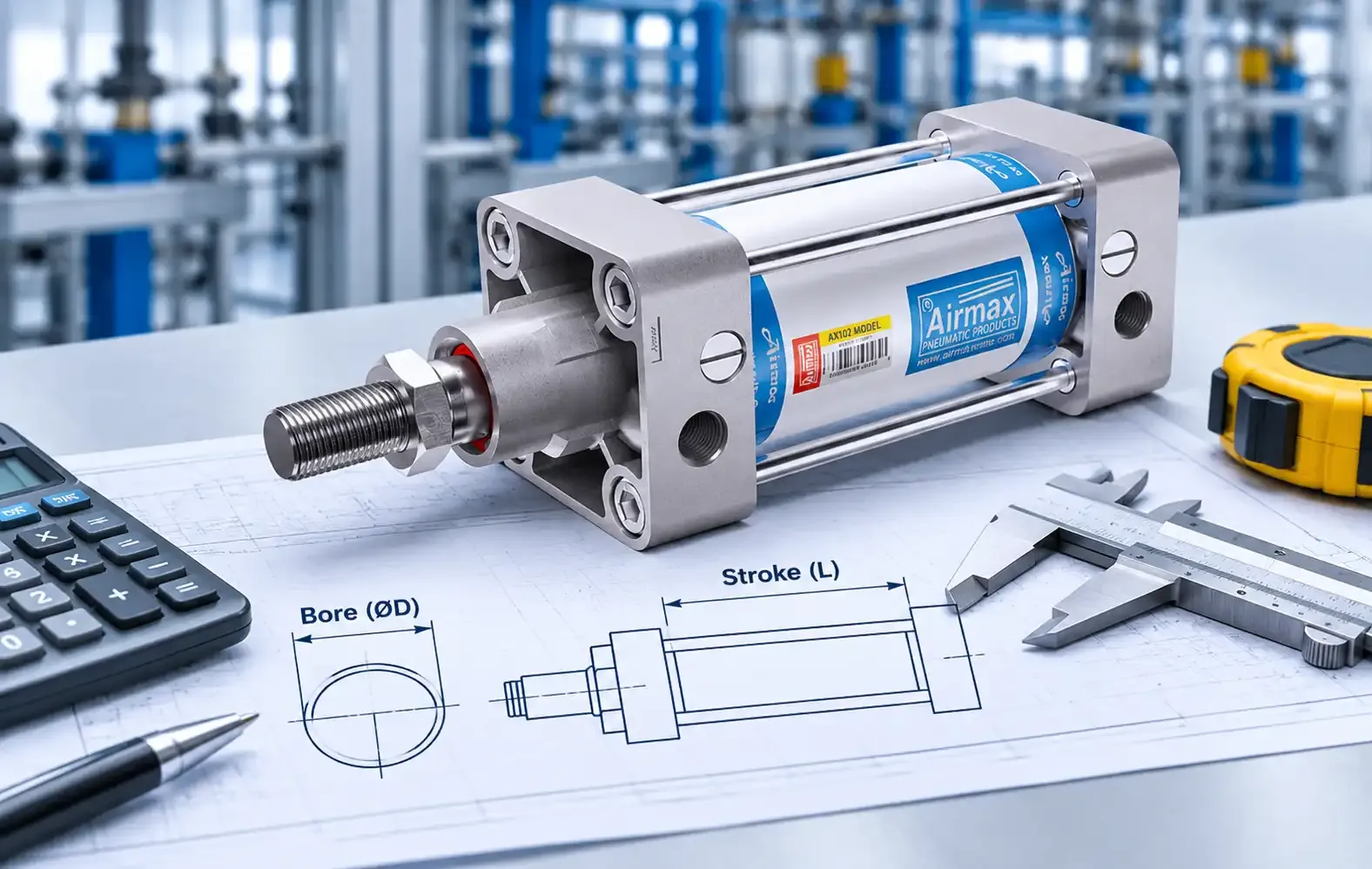
Picking a cylinder sounds easy until you do it. Go too small and the load will not move, or it moves slowly and stalls. Go too big and you pay more, use more air and may not fit the space. Two numbers decide most of this: the bore, which sets how hard the cylinder can push, and the stroke, which sets how far it can travel.
This guide walks through both calculations in plain steps. You will see the formulas, a worked example in metric units, a table of standard bore sizes, and the one check on long strokes that people often skip. You only need basic arithmetic.
What bore and stroke actually decide
Bore is the inside diameter of the cylinder barrel, which is the diameter of the piston. A larger bore gives more force at the same air pressure [5].
Stroke is the distance the piston rod travels. It decides the type of cylinder and the space the cylinder needs when mounted [1].
Force comes from pressure acting on area, so bore is a force calculation. Stroke is mostly a measurement of your machine, with a safety check added for long strokes.
Step 1: Work out the force you need
Start with the force needed to move the load. One selection guide says the cylinder’s force should be slightly higher than the force required to move the load [7]. That small gap matters, because friction and pressure drop in lines and valves make the real force lower than the theoretical maximum [7].
Two sources suggest a margin, and they do not agree on how big it should be:
Neither is a law. A light, smooth load needs less margin than one that has to start against friction or a shock. Pick a factor you can explain, write it down, and use the same one every time.
Two more points to remember:
Step 2: Calculate the bore
The core formula is simple. Force equals pressure times area [7]. For a round piston, the area is a = (π/4) × D², where D is the bore diameter [7].
Rearranged to find the bore, the formula becomes D = √(4F ÷ (π × P)), where F is the force you need and P is the pressure [2].
Unit tip: 1 bar is 100,000 Pa [3], which is the same as 0.1 N/mm². So 6 bar is 0.6 N/mm². Using newtons, millimetres and N/mm² keeps everything in one set of units.
Worked example
Say a clamp must push with 1,000 N, and you have 6 bar available at the cylinder. This is my own example, built with the formulas above.
A 50 mm bore would give only about 1,178 N at 6 bar before any losses, which is below the 1,500 N target. If you use the 25% factor instead [2], the target is 1,250 N, the calculated bore is about 51.5 mm, and the answer is still 63 mm.
Theoretical push force by standard bore
This table is my calculation from the formula above, at 6 bar. It does not include friction or a safety factor, so treat it as the upper limit. The bore sizes come from ISO 15552 [4].
| Bore (mm) | Piston area (mm²) | Push force at 6 bar (N) |
| 32 | 804 | 483 |
| 40 | 1,257 | 754 |
| 50 | 1,963 | 1,178 |
| 63 | 3,117 | 1,870 |
| 80 | 5,027 | 3,016 |
| 100 | 7,854 | 4,712 |
| 125 | 12,272 | 7,363 |
| 160 | 20,106 | 12,064 |
| 200 | 31,416 | 18,850 |
| 250 | 49,087 | 29,452 |
| 320 | 80,425 | 48,255 |
Use the pressure you really have
One sizing guide says the supply side needs to allow for losses: about 5% more pressure to cover cylinder losses, and 25 to 50% more for flow losses in lines and valves, so the cylinder reaches a reasonable travel speed [2]. In other words, the gauge reading at the compressor is not the pressure at the cylinder. Use the lower number when you size the bore, and look at your piping, fittings and valves if the two are far apart.
Step 3: Check the pull stroke
On a double acting cylinder, the rod takes up part of the piston area on the rod side. Air pushes only on the ring-shaped area left over, which is the piston area minus the rod area [1]. That is why the pull force is lower than the push force [6].
The formula from one calculator site, which also includes an efficiency factor for seal friction, is: pull force = pressure × (π/4 × (D² − d²)) × η, where d is the rod diameter. The page gives a typical efficiency range of 0.85 to 0.95 [3].
Using the same example, a 63 mm bore at 6 bar with an assumed 20 mm rod (the rod size used in that calculator’s worked example [3]; check your own cylinder’s datasheet):
Using an efficiency of 0.90, the push is about 1,683 N and the pull is about 1,514 N. The push figure matches the example shown on the calculator page [3], and I worked out the pull from its formula.
So the pull is about 90% of the push here. If your load is heavier on the return stroke, check this number and not just the push force. The pattern holds in other units too: one guide shows a 4 inch cylinder with a 1 inch rod having 11.78 square inches of effective area on the pull side, against 12.57 on the push side [2].
Step 4: Choose the stroke
Stroke starts with a measurement: how far does the load have to move? The examples in one specification guide show how widely this varies, from a fraction of an inch for staking a rivet to about 2 inches for a conveyor stop gate, and 30 inches or more for pushing a load off a conveyor [1]. The same guide sorts cylinders into short, intermediate, long and specialty types, and points out that stroke decides the cylinder type and the space needed to mount it [1].
Some practical points:
Step 5: Check long strokes for buckling
A double acting cylinder has no fixed stroke limit, but a long, thin piston rod is more prone to buckling and bending, so extra calculations are needed [6]. One reference gives a rule of thumb: if the rod length is under 10 times its diameter, it can be treated as a rigid body. If it is longer, it should be treated as a column and checked for buckling [6].
Buckling is a risk while the rod is extended and pushing, because it is under compression. While pulling, it is mainly in tension [5]. The factors that matter most are [5]:
The source lists safety factors from manufacturers of 3.5 to 5 for this check, and says the right value must come from the exact product documentation [5]. A larger bore also raises the push force at the same pressure, which can make the compression load worse [5]. Where the numbers look tight, the usual fixes are a thicker rod, a shorter effective length, guiding the load externally, or a different type of actuator [5]. For anything long or heavily loaded, ask the manufacturer to run the check.
Common mistakes to avoid
Quick reference
| Question | Formula or rule | Source |
| Piston area | A = (π/4) × D² | [7] |
| Push force | F = P × A (× efficiency, if used) | [3][7] |
| Bore from force | D = √(4F ÷ (π × P)) | [2] |
| Pull force | P × (π/4)(D² − d²) | [3] |
| Safety margin | 25% or 50% suggested, depending on the guide | [1][2] |
| Rod check | Treat as a column if longer than 10 × diameter | [6] |
Airmax pneumatic cylinders
Airmax Pneumatics Ltd has made pneumatic products in Ahmedabad since 1992. Our pneumatic cylinder page lists single acting and double acting cylinders in sizes from 12 mm to 500 mm bore. Strokes are listed from 10 mm to 2000 mm, while our heavy-duty section and FAQ mention strokes up to 2500 mm, so please confirm the stroke for your bore with our team [8]. Barrels are available in aluminium, stainless steel, and mild steel with a honed, hard chrome plated bore [8].
Our heavy-duty cylinders are described as handling 12 kg/cm² pressure and temperatures up to 180°C with heat-resistant seals [8]. Always check the datasheet for the specific model before you design to those numbers.
Some models to start with:
Once the cylinder is chosen, the rest of the circuit needs matching. You will need a directional control valve to send the air, FRL units to filter and regulate it, moisture separators to keep water out, and fittings and accessories to connect it all.
If you want to go deeper, our post on how a double acting pneumatic cylinder works explains the working principle, and our pneumatic vs hydraulic comparison helps when the force you need is very high. To keep cylinders working well after installation, see our preventive maintenance checklist and our guide to finding and fixing compressed air leaks.
Not sure which size to pick?
Send us your load, the stroke you need, the pressure at the machine and how the cylinder will be mounted. Our team can help you check the bore, the rod and the stroke before you order. You can contact us here or download the product catalogue.
References
- Walling, J. “Keys to specifying pneumatic cylinders.” Pneumatic Tips (Fabco-Air), February 2015. https://www.pneumatictips.com/keys-specifying-pneumatic-cylinders/
- AutomationDirect. “Cylinder Sizing & Force.” https://www.automationdirect.com/pneumatics/cylinders/cylinder_sizing
- RedCrab Software. “Pneumatic Cylinder Calculator.” https://www.redcrab-software.com/en/Calculator/Physics/Air-Cylinder
- Simonson, S. L. “ISO 15552 Pneumatic Cylinders.” Tameson, 2023 (updated 2025). https://tameson.com/pages/iso-15552-pneumatic-cylinders
- Chen, J. “How Can You Prevent Piston Rod Buckling in Long-Stroke Cylinder Applications?” Bepto Pneumatic, 2025 (updated 2026). https://rodlesspneumatic.com/blog/how-can-you-prevent-piston-rod-buckling-in-long-stroke-cylinder-applications
- Wikipedia. “Pneumatic cylinder.” https://en.wikipedia.org/wiki/Pneumatic_cylinder
- MISUMI. “Basics for selecting pneumatic cylinders.” https://uk.misumi-ec.com/en/techblog/general-info/basics-for-selecting-pneumatic-cylinders
- Airmax Pneumatics Ltd. “Pneumatic Cylinder.” https://www.airmaxindia.com/products/pneumatic-cylinder/